





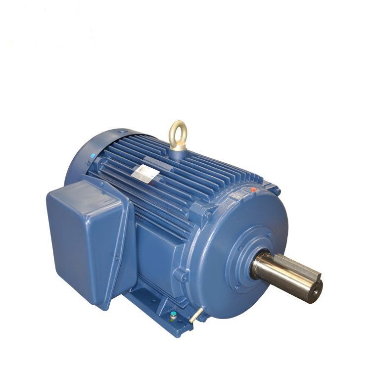
What Is a Synchronous Motor? Definition, Types & Working Principle
If you are researching AC motor solutions for industrial equipment, you may ask: what is a synchronous motor? A synchronous motor is an alternating‑current (AC) electric motor whose rotor spins at exactly the identical speed as the stator‑generated rotating magnetic field. Its shaft speed stays constant and locked to the frequency of incoming AC power supply. Thanks to this magnetic‑locking feature, it stands out for scenarios demanding accurate, steady‑speed performance.
Many people understand electric motors convert electricity into mechanical motion, yet few realize how many different design paths engineers adopt to achieve energy conversion. Some motors run on DC power, some on AC power, and others combine both power inputs. Each motor category applies unique energy‑transfer mechanisms. That creates a wide portfolio of DC and AC motors, each bringing distinctive strengths for specific operating conditions.
What is a Synchronous Motor?
To fully answer what is a synchronous motor, we need to compare it against induction motors, another mainstream AC motor family.
Induction motors rely on electromagnetic induction to output mechanical power. Their key limitation is slip — a speed gap between AC supply oscillation frequency and actual rotor rotation speed. Caused by induction‑driven torque generation, slip makes standard induction motors (also named asynchronous motors) unsuitable for jobs calling for strict timing precision.
A synchronous motor eliminates slip. Its output rotational frequency perfectly matches input AC frequency. This property makes it fit for clocks, rolling mills, record players and other precision‑critical devices. Though synchronous motors cannot match induction motors in overall power scope and model variety, they occupy an irreplaceable position wherever precise timing and rigid speed stability are required.
Are you looking for reliable synchronous motor products? Feel free to contact us for further support.
Key Components of a Synchronous Motor
Every functional synchronous motor depends on coordinated work among multiple core mechanical‑electrical parts. Below introduces major components and their respective functions:
1. Stator
The stator is the stationary frame part of the motor. It is stacked from silicon‑steel stampings with inner slots to hold winding coils. The stator undertakes the core task of building the rotating magnetic field essential for motor operation.
2. Stator Winding
Stator winding is normally fabricated from heavy‑duty super‑enamelled copper wire. It adopts three‑phase star or delta connection layout and inserts into stator slots. Once energized by three‑phase AC source, the winding generates the rotating magnetic field.
3. Rotor
The rotor represents the rotating assembly. Its outer circumference mounts magnetic poles, and its main body is also laminated silicon‑steel sheets. This material choice optimizes magnetic performance and cuts down energy loss.
4. Rotor Winding
Enamelled copper wire forms rotor winding, which wraps around rotor magnetic poles. It receives DC current delivered by the exciter and establishes the rotor magnetic field for magnetic locking with the stator rotating field.
5. Exciter
The exciter is a small‑rated DC shunt generator mounted on the same shaft together with the rotor. During motor running, it produces DC excitation current fed to rotor windings, forming a self‑sustaining excitation supply loop.
6. Slip‑Rings and Brushes
Two phosphor‑bronze slip‑rings install on the rotor shaft. Carbon brushes keep continuous physical contact against slip‑rings. This assembly transmits DC excitation power from exciter toward rotor winding for stable power transfer.
Main Characteristics of Synchronous Motors
- No inherent self‑starting capability: Synchronous motors need external auxiliary means to accelerate rotor speed near synchronous speed before magnetic synchronization can take place.
- Constant‑speed performance: Under fixed grid frequency, its operating speed remains unchanged regardless of load fluctuation.
- Adjustable power factor: A unique advantage — synchronous motors can run at lagging, unity or leading power factor. Engineers leverage this trait to improve overall system electrical power factor.
Applications of Synchronous Motors
- Power‑factor correction: Since synchronous motors support both leading and lagging power‑factor operation, they serve as reactive‑power compensation equipment. At no‑load status, they work with leading power factor, applicable for power‑grid sites where static capacitor banks cannot be deployed.
- Low‑speed high‑power industrial drives: They are widely equipped for mills, chippers, agitators, large pumps, compressors and other heavy‑duty low‑speed facilities.
How Does a Synchronous Motor Work?
Similar to induction motors, a synchronous motor consists of outer stator and inner rotor, generating shaft torque via magnetic interaction. It supports single‑phase or multi‑phase AC input depending on motor size and application scenarios.
Its stator shares identical construction with induction motors: copper or aluminum coils embedded in laminated steel cores. AC flowing through coils builds the rotating magnetic field (RMF). The biggest structural difference lies on the rotor. The rotor carries permanent magnetic poles, produced either by built‑in permanent magnets or DC‑energized rotor coils. These fixed north‑south rotor poles will eventually align with poles of the stator rotating magnetic field, delivering rotation strictly proportional to supply frequency. Rotor poles can stick out (salient‑pole rotor) or embed inside core slots (non‑salient‑pole rotor).
One critical point: the motor cannot pull‑in synchronism at stand‑still. Large speed difference between stationary rotor and fast‑spinning RMF prevents magnetic pole locking at startup. According to rotor excitation solutions, synchronous motors are grouped into non‑excited synchronous motors and current‑excited synchronous motors.
Working Principle of Synchronous Motor
A synchronous motor counts as a double‑excitation machine accepting two separate electric inputs: three‑phase AC for stator windings and DC for rotor windings. Three‑phase stator current creates rotating magnetic flux, while DC‑powered rotor produces steady constant magnetic flux.
At any given instant, rotor and stator magnetic polarities may coincide and generate repulsion force; moments later they turn N‑S opposite and create attraction torque. Nevertheless, rotor mechanical inertia stops the shaft from spinning back and forth under alternating attractive/repulsive impulses. Consequently, the rotor keeps stationary. This explains why a synchronous motor cannot start by itself.
Practically, external mechanical drive equipment spins the rotor toward the same rotation direction as stator RMF, bringing rotor speed close to synchronous speed. Once hitting synchronous speed, magnetic locking takes effect. Even after removing the auxiliary driving source, the synchronous motor keeps steady rotation.
Want to get your free project quotation? Please reach out to our team.
Types of Synchronous Motors
We classify synchronous motors based on how rotors obtain excitation to achieve synchronous running: non‑excited synchronous motors and current‑excited synchronous motors.
Non‑excited Synchronous Motors
Non‑excited synchronous motors require no external excitation voltage for startup. Their rotors use ferromagnetic materials to interact magnetically with stator fields. Three mainstream sub‑types are hysteresis motors, synchronous reluctance motors and permanent‑magnet motors.
- Hysteresis motors: The rotor shaft is wrapped with a ferromagnetic hysteresis ring over non‑magnetic substrate material. The stator rotating magnetic field induces magnetic poles on this ring. Hysteresis energy loss creates phase lag between rotor flux and stator flux, producing output torque. Hysteresis motors run quietly and suit record players, tape recorders and other audio‑related precision devices.
- Synchronous reluctance motors: They produce rotation by magnetic attraction and reluctance effects. The stator carries prominent coil‑wound poles. The ferromagnetic rotor adopts modified squirrel‑cage geometry with recessed barriers and slots. When rotor poles misalign against stator magnetic‑field lines, magnetic reluctance rises. The rotor naturally tends to move toward low‑reluctance aligned positions and generates reluctance torque. Certain designs can pull rotor into synchronous speed and deliver precise rotary output.
- Permanent‑magnet synchronous motors: Permanent magnets mounted inside or on rotor surface provide constant magnetic flux, which couples with stator RMF for rotation. Variable‑frequency drives are mandatory for speed and torque adjustment, because modifying stator AC frequency is the only method to change motor output performance.
Current‑excited Synchronous Motors
DC‑excited synchronous motor represents the primary current‑excited synchronous motor type. It requires dual power supplies: AC for stator and DC for rotor windings. DC feeds rotor coils to build stable rotor magnetic field. Rotor magnetic poles align with stator rotating magnetic field and realize synchronization. These motors usually rate above 1 horsepower. When industrial professionals mention "synchronous motor", they mostly refer to this widely‑adopt DC‑excited design.
Without synchronous‑motor technology, many familiar devices would not exist: clocks, record players, windshield wipers, hard disk drives, signaling apparatus, recording meters and timing‑control boards all rely on synchronous‑motor characteristics. Beyond precise timing performance, high‑efficiency synchronous motors compensate induction‑motor system losses and mitigate power‑distribution waste. Even though synchronous motors carry higher cost and more complex structures compared with induction motors, they remain irreplaceable industrial workhorse for power‑factor correction and high‑accuracy motion control.
Summary
This article answers what is a synchronous motor, and further covers its core definition, internal components, key features, working mechanisms, classification and typical use‑cases. We hope this technical overview brings value for your motor‑selection work. If you need more details on synchronous‑motor products, do contact us anytime.
