





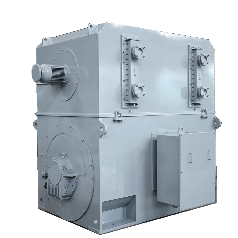
What Are Synchronous Motors? What They Are and How They Operate
A synchronous motor is an AC electric motor whose rotor spins at exactly the same speed as the rotating magnetic field generated by the stator. It runs at a constant speed synchronized with supply‑power frequency. Fundamentally, the rotor magnetically locks with the stator’s magnetic field, making it well‑suited for applications demanding precise speed control.
Most people know electric motors convert electricity into mechanical motion, yet few understand the diverse working principles behind this conversion. Though it might seem unnecessary to develop multiple motor types for the same goal, there are solid engineering justifications. Motors can operate on DC power, AC power, or a hybrid of both, with each category adopting unique energy‑transfer mechanisms. Consequently, numerous DC and AC motor variants exist, each bringing distinct advantages to specific operating scenarios.
Synchronous motors belong to the AC motor family, developed to overcome certain limitations of induction motors — another widely‑used type of AC motor. As its name suggests, an induction motor produces mechanical energy via electromagnetic induction. Its primary weakness lies in slip: a speed gap between the AC supply frequency and actual rotational speed, an inherent outcome of induction‑driven rotation. Slip is negligible for many general‑purpose uses, yet it disqualifies ordinary induction motors from precision‑timing tasks, hence they are named asynchronous motors.
By contrast, synchronous motors deliver an output rotational frequency identical to the input AC frequency. Thanks to speed directly proportional to supply AC power, they find uses in clocks, rolling mills and record players. While they cannot match induction motors in power output or model diversity, synchronous motors occupy a critical position in projects requiring accurate timing and steady rotational speed.
Key Components of a Synchronous Motor
Several vital parts work cooperatively to guarantee stable, efficient performance. The major components and their functions are listed below:
- Stator
The stator is the stationary portion of the motor. Fabricated from silicon‑steel laminations, it features inner slots for holding windings. Its core function is to generate the rotating magnetic field for motor operation. - Stator Winding
Commonly made of heavy‑duty enamelled copper wire, the stator winding adopts three‑phase star or delta connections and fits inside stator slots. Energized by three‑phase AC supply, it produces the rotating magnetic field. - Rotor
The rotor is the rotating element. This cylindrical structure has magnetic poles on its outer surface. Like the stator, it is built from silicon‑steel laminations to optimize magnetic performance and cut energy losses. - Rotor Winding
Enamelled copper wire is wound around rotor poles to form the rotor winding. Supplied with direct current from the exciter, it builds up the magnetic field that magnetically locks the rotor to the stator’s rotating magnetic field. - Exciter
The exciter is a small‑capacity DC shunt generator mounted on the same shaft as the rotor. During motor operation, it generates DC excitation current fed into rotor windings, forming a self‑sustaining excitation supply. - Slip‑Rings and Brushes
Two phosphor‑bronze slip‑rings are fitted onto the rotor shaft. Carbon brushes keep continuous physical contact with slip‑rings, transmitting DC excitation current from the exciter to rotor windings for reliable power transfer.
Main Characteristics of Synchronous Motors
- Synchronous motors possess no inherent self‑starting capability. Auxiliary external means are required to bring rotor speed close to synchronous speed before magnetic synchronisation can take place.
- Running speed is locked to supply frequency. With constant grid frequency, they maintain constant rotational speed irrespective of load variations.
- They feature adjustable power‑factor operation, which enables them to improve overall system power factor.
Applications of Synchronous Motors
- Capable of operating under leading or lagging power factors, synchronous motors can boost power‑factor performance. Running with leading power factor under no‑load conditions, they can be deployed in power systems where static capacitors are not feasible.
- They serve low‑speed, high‑power scenarios, including mills, chippers, agitators, large pumps and compressors.
How Does a Synchronous Motor Work?
Similar to slip‑ring induction motors, a synchronous motor consists of an outer stator and an inner rotor, producing output torque through magnetic interactions. Depending on size and application, it may run on single‑phase or multi‑phase AC input.
Its stator shares the same construction as induction motors, with copper or aluminium coils embedded in laminated steel sheets. Alternating current passing through these coils creates a rotating magnetic field. The main difference lies in the rotor: it carries a permanent magnetic field, either from built‑in permanent magnets or DC‑energized rotor windings. Equipped with fixed north‑south magnetic poles, the rotor aligns with poles of the stator rotating magnetic field, yielding rotational speed strictly proportional to stator supply frequency. Rotor poles can protrude outwards or sit within slots, known as salient‑pole and non‑salient‑pole rotors respectively.
External excitation assistance is necessary for startup. At standstill, the stationary rotor cannot instantly lock onto the fast‑spinning rotating magnetic field. Based on startup‑excitation methods, synchronous motors fall into two categories: non‑excited synchronous motors and current‑excited synchronous motors.
Working Principle of Synchronous Motor
A synchronous motor is a double‑excited machine receiving two separate electrical inputs: three‑phase AC for stator windings and direct current for rotor windings. Three‑phase current in stator windings generates a rotating magnetic flux; DC fed to the rotor produces a steady constant flux.
At any instant, rotor and stator poles may repel each other, while moments later opposite poles attract. Restrained by rotor inertia, these alternating attraction‑repulsion forces cannot set the stationary rotor into rotation. This explains why synchronous motors cannot self‑start.
Auxiliary mechanical equipment accelerates the rotor to near‑synchronous speed in the same rotational direction as the stator magnetic field. Once reaching synchronous speed, magnetic locking takes effect. The motor keeps rotating steadily even after removing the external driving mechanism.
Types of Synchronous Motors
Synchronous motors are classified by rotor excitation approaches: non‑excited synchronous motors and current‑excited synchronous motors.
Non‑excited Synchronous Motors
This type needs no external excitation voltage. Its ferromagnetic rotor interacts directly with the stator magnetic field. Three common subtypes are hysteresis motors, synchronous reluctance motors and permanent‑magnet synchronous motors.
- Hysteresis motors: Their rotor shaft is wrapped with a ferromagnetic hysteresis ring set in non‑magnetic material. The stator rotating magnetic field induces magnetic poles on the ring. Hysteresis energy loss creates an angular offset between rotor and stator magnetic fields, generating output torque. Running with low noise, they are widely used in record players, tape recorders and other audio equipment.
- Synchronous reluctance motors: They produce torque via magnetic attraction and reluctance effects. In structure they resemble stepper and induction motors; the stator has coil‑wound salient poles generating magnetic fields. The ferromagnetic rotor is modified from squirrel‑cage structures, with slots and barriers. Magnetic reluctance rises when rotor and stator poles are misaligned. To minimise reluctance, reluctance torque pulls the rotor toward aligned positions, enabling pull‑in to synchronous speed and precise rotation.
- Permanent‑magnet synchronous motors: Rotor‑mounted permanent magnets supply constant magnetic flux, which interacts with the stator rotating magnetic field to drive rotation. Variable‑frequency drives are mandatory for speed and torque regulation, as performance adjustment relies entirely on modifying stator AC supply frequency.
Current‑excited Synchronous Motors
DC‑excited synchronous motors represent the major category here, requiring both AC stator supply and DC rotor supply. Direct current flows into rotor windings comparable to stator coils, building constant rotor magnetic fields. Excitation enables pole alignment with the stator rotating magnetic field to achieve synchronisation. Most units are rated above 1 horsepower; in industry, the term “synchronous motor” usually refers to this configuration.
Synchronous motors are irreplaceable complement to induction motors. Without them, clocks, record players, windscreen wipers, hard disk drives, signalling apparatus, recording instruments and various timing devices would not exist. Beyond precision rotation, they improve system efficiency and mitigate distribution losses caused by induction‑motor drawbacks. Despite higher cost and complexity compared with induction motors, synchronous motors deliver valuable power‑factor correction and high‑accuracy motion for modern industrial design.