


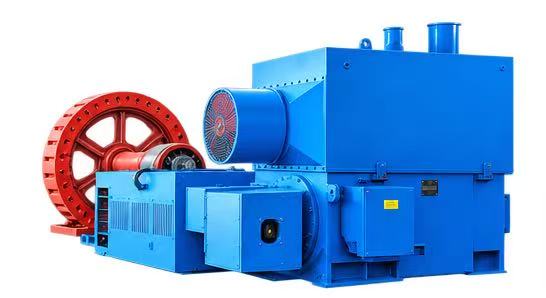
Three Phase Induction Motors Internal Structure Types And Induction Motor Parts
Electric motors transform electrical energy into mechanical energy. In this post, we explore how three‑phase motors work, their key induction motor parts, and real‑world applications.
Nearly 80% of industrial motors are three‑phase induction motors, making them the most widely adopted motor type across industry sectors.
Internal Composition & Key Induction Motor Parts
A three‑phase induction motor belongs to AC motors powered by three‑phase mains, unlike single‑phase induction motors that run on single‑phase power. Three‑phase current feeds the stator winding and creates a rotating electromagnetic field; this magnetic field induces current in the rotor and generates output torque.
Known for simple, heavy‑duty build, the core induction motor parts fall into two major assemblies: stator and rotor.
Stator (stationary assembly of induction motor parts)
The stator is the non‑rotating section of the motor, built from three critical induction motor parts: stator frame, stator core and stator winding.
- Stator frame
The stator frame forms the motor’s outer housing. It mechanically supports the stator core and stator windings, delivering structural rigidity for all internal induction motor parts. Frames may be cast steel, fabricated steel, aluminium alloy or stainless steel, selected according to operating conditions. - Stator core
The stator core carries alternating magnetic flux. Hysteresis loss and eddy‑current loss occur within this component. Thin metal laminations are coated with insulating varnish, stacked and secured inside the stator frame to form the complete stator‑core assembly. - Stator winding
Stator windings sit inside slots cut into the stator core. Three‑phase windings are fitted here and supplied with three‑phase power. Internal winding connections set the motor pole count, which directly governs synchronous motor speed.
Rotor (rotating assembly of induction motor parts)
The rotor is the rotating set of induction motor parts. Based on rotor design differences, induction motors split into squirrel‑cage induction motors and slip‑ring (wound‑rotor) induction motors. Both variants share identical stator induction motor parts. Rotor‑design differences define the main three‑phase induction motor types explained below.
Types of Three‑Phase Induction Motors
Classified by rotor‑winding construction, the two primary categories are squirrel‑cage motors and slip‑ring motors.
Squirrel‑cage Induction Motors
Its rotor assembly looks like a squirrel cage, hence the name. This rotor ranks among the most durable induction motor parts; roughly 80% of installed induction motors are squirrel‑cage type.
The rotor uses a stacked laminated cylindrical core with skewed outer slots. Skewing avoids magnetic locking between stator and rotor teeth, suppresses acoustic hum and delivers smoother operation.
Instead of traditional wound coils, conductive rotor bars (aluminium, brass or copper) form the circuit. No slip rings or brushes are required, delivering a simplified, rugged set of induction motor parts.
Slip‑ring Induction Motors
Also named wound‑rotor motors.
This rotor consists of a laminated cylindrical core with outer slots holding dedicated rotor windings. Rotor windings are wound to match the stator pole number and can be configured for star or delta connection. Winding terminals connect to slip‑ring induction motor parts mounted on the shaft, giving this motor its slip‑ring title.
Near full operating speed, slip rings get short‑circuited via metal rings. Brushes and external resistors can then be disconnected from the rotor circuit, cutting rotor copper loss and brush friction loss. Overall, its rotor‑related induction motor parts are more complex than those of squirrel‑cage models.
