





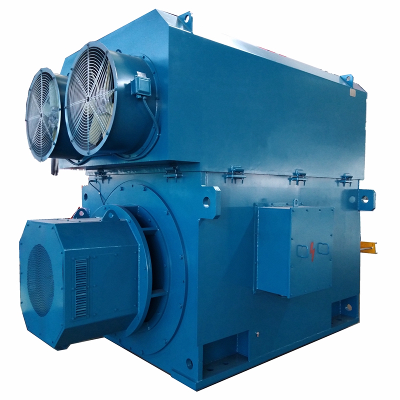
Key Components and Working Mechanisms in an AC Motor Diagram
An ac motor diagram is an essential visual tool for understanding how these machines convert electrical energy into mechanical motion. Used across industrial, commercial, and residential applications, an AC motor fundamentally consists of two main parts: the stationary stator and the rotating rotor. By analyzing an ac motor diagram, one can easily visualize how alternating current flowing through the stator windings generates a rotating magnetic field, which is the core principle behind the motor's operation.
Understanding the AC Motor Diagram: Core Components
When examining a detailed ac motor diagram, two primary components stand out:
- The Stator: This is the stationary outer part of the motor. As shown in most ac motor diagrams, the stator consists of a laminated iron core and copper wire coils. In three-phase motors, these windings are positioned 120° apart. When AC voltage is applied, the stator acts as both the armature and field winding, creating a rotating magnetic field that moves at synchronous speed.
- The Rotor: The rotating inner part connected to the motor shaft. An ac motor diagram illustrates that unlike DC motors, the rotor has no direct external power connection. Instead, it receives power through electromagnetic induction from the stator's magnetic field.
Types of AC Motors in Diagrammatic View
AC motor diagrams vary depending on the specific type of motor being illustrated. The main distinction lies in the electrical supply and intended application:
- Single-Phase Motors: Commonly depicted in residential ac motor diagrams, these require single or double-phase power and often include a capacitor to initiate the rotating magnetic field.
- Three-Phase Motors: Standard in industrial ac motor diagrams, these utilize three-phase power to create a naturally smooth and continuous rotating magnetic field.
- Most of these motors are induction motors, meaning the diagram must show how the stator's magnetic field induces a current in the rotor to generate torque.
Rotor Configurations: Squirrel Cage vs. Wound Rotor
A technical ac motor diagram will clearly differentiate between the two main rotor types:
- Squirrel Cage Rotor: The most common type shown in an ac motor diagram. It consists of aluminum or copper bars connected by end rings, resembling a hamster wheel. The fluctuating stator field induces current in these bars, causing rotation. The diagram helps explain the concept of "slip"—the rotor must rotate slightly slower than the stator's magnetic field to induce current; if they matched speeds, torque would drop to zero.
- Wound Rotor (Slip Ring): This ac motor diagram features a cylindrical core with wire windings connected to slip rings and brushes on the shaft. This setup allows for external resistance to be added, providing precise control over speed and torque, which is ideal for heavy-duty industrial applications.
Starting Methods Illustrated
An ac motor diagram focusing on control circuits will illustrate various starting methods designed to prevent electrical and mechanical damage:
- Contactor/Manual Starter: Simple on/off power control.
- Star-Delta Starter: The diagram shows windings initially connected in a star (Y) configuration to reduce starting current, then switching to delta (Δ) for full voltage.
- Auto-Transformer & Rotor Impedance Starters: These diagrams highlight how voltage or rotor resistance is manipulated to limit initial current.
- Soft Starters: Electronic diagrams showing a gradual ramp-up of power to reduce mechanical wear.
Conclusion and Practical Application
Whether you are studying a basic residential ac motor diagram or a complex three-phase industrial schematic, understanding these visual representations is key to grasping motor functionality. The seamless interaction between the stator and rotor makes AC motors incredibly versatile and reliable.
For businesses looking to source components based on these diagrams, the Y2 series asynchronous motor is a prime example of modern engineering. With a center height of H80-355mm, this fully enclosed, self-fan cooled squirrel cage three-phase motor is designed for general-purpose low-voltage use. Building on the reliable Y series, the Y2 offers higher power, increased starting torque, IP54 protection, and F-class insulation. Its noise-reduced design and IC411 cooling method ensure optimal performance, making it a cost-effective, bulk-procurement solution for industrial operations.
