





How Does an AC Electric Motor Work? Understanding Its Core Components
An AC electric motor is a fundamental piece of machinery that converts alternating current (AC) electrical energy into mechanical energy. This conversion is achieved through the principles of electromagnetism and electromagnetic induction. The operation of the motor relies on the interaction between two primary components: the stator (the stationary outer part) and the rotor (the rotating inner part connected to the motor shaft).
The Creation of a Rotating Magnetic Field
The process begins when an AC voltage is applied to the stator windings. In three-phase AC motors, these windings are positioned 120° apart. As the alternating current flows through them, it generates a rotating magnetic field that moves at a synchronous speed. This rotating magnetic field acts as the driving force for the entire motor.
Electromagnetic Induction and Torque Generation
Unlike DC motors, the rotor in a standard AC induction motor has no direct electrical connection to an external power source. Instead, it receives its power inductively. The stator’s rotating magnetic field cuts across the rotor's conductors, inducing a voltage and, consequently, an electric current within the rotor. This induced current creates its own magnetic field around the rotor. The interaction between the stator's rotating magnetic field and the rotor's induced magnetic field generates an electromagnetic force (torque), which causes the rotor to spin.
The Concept of "Slip"
A defining characteristic of asynchronous (induction) AC motors is that the rotor never quite catches up to the speed of the stator's rotating magnetic field. If the rotor were to rotate at the exact same frequency (synchronous speed), there would be no relative motion between the magnetic field and the rotor conductors, meaning no current would be induced and no torque would be generated. This difference in speed between the rotating magnetic field and the actual rotor speed is known as "slip," and it is essential for the continuous production of motion.
Types of Rotors and Starting Methods
The design of the rotor dictates specific motor characteristics. The most common type is the squirrel cage rotor, which consists of aluminum or copper bars shorted by end rings. These are favored for their simplicity, reliability, and low cost. For applications requiring precise control over speed and torque, a wound rotor is used. This rotor features wire windings connected to slip rings and brushes, allowing external resistance to be added to the circuit for fine-tuning performance.
To prevent mechanical stress and electrical damage during startup, various methods are employed to control the initial power supply. These include simple contactor or manual starters, Star-Delta starters that reduce initial voltage, auto-transformer starters, and modern soft starters that provide a smooth, gradual acceleration.
Practical Applications and the Y2 Series Solution
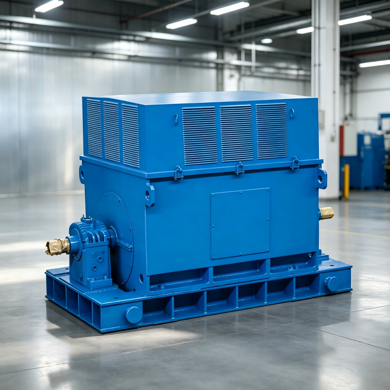
AC motors are ubiquitous, with single-phase motors powering residential appliances and three-phase motors driving heavy industrial machinery. For businesses seeking a robust and efficient solution for bulk procurement, the Y2 series asynchronous motor stands out as an exceptional choice. Building on the reliable Y series, the Y2 motor (center height H80-355mm) is a fully enclosed, self-fan cooled squirrel cage three-phase motor designed for general-purpose low-voltage use.
The Y2 series offers significant upgrades, including higher power, increased starting torque, and enhanced durability with an IP54 protection class and F insulation class. Its noise-reduced design and IC411 cooling method ensure optimal performance and efficiency, fully meeting IEC standard specifications. By choosing the Y2 series, companies can secure a cost-effective, high-reliability power source that reduces long-term maintenance costs and supports demanding industrial and commercial operations.
