


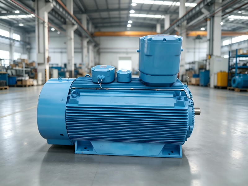
AC Motors and Types: Fundamentals of Operation and Main Components
AC motors are essential pieces of machinery deployed across diverse industrial, commercial, and residential scenarios. Two fundamental parts make up an AC motor: the stationary outer stator and the rotating inner rotor coupled to the motor shaft. Both components produce rotating magnetic fields, which lie at the heart of motor functioning. The stator builds its rotating magnetic field when alternating current flows through its internal windings.
Within an AC motor, stator windings perform dual‑role duties, acting as both armature and field windings. Once AC voltage feeds into the stator, a rotating magnetic field spinning at synchronous speed comes into being. This magnetic field induces voltage in windings of both stator and rotor, enabling the motor to run.
AC motors cover multiple categories, each engineered for targeted working conditions. Major variants include single‑phase, three‑phase, brake, synchronous, asynchronous, custom‑built, two‑speed and three‑speed motors. Their primary distinctions stem from application scenarios and input power supply requirements.
Residential‑grade equipment mostly runs on single‑phase or double‑phase power supplies.
Conversely, industrial facilities widely adopt three‑phase power supplies.
Such power‑supply differences mark a clear boundary between industrial‑use and residential‑use AC motors.
The bulk of AC motors fall into the induction motor family. They generate torque via electromagnetic induction. The magnetic field from the stator triggers current flow inside the rotor, which further yields torque and drives mechanical rotation.
Starting Methods for AC Motors
Multiple starting approaches are available for AC motors, selected according to motor categories and practical working conditions. These methods regulate input power to deliver soft startup performance and guard against electrical and mechanical damage.
Contactor or Manual Starter
Contactors deliver convenient on‑off power control for motors. Manual starters give operators direct handling authority through manual switches to govern power supply.
Star‑Delta Starters
This solution cuts down voltage fed to motors at startup. Stator windings are initially wired in star (Y) connection to suppress starting current. After the motor accelerates to a predefined speed, windings switch over to delta (Δ) connection for full‑voltage operation.
Auto‑Transformer Starter
It also restricts inrush current by lowering stator input voltage during startup. Users can adjust output torque and starting current flexibly by tapping different transformer terminals.
Rotor Impedance Starter
It connects to rotors directly via slip rings and brushes. Rotor resistance is set to maximum value at the initial startup phase and gradually drops as the motor speeds up. Though functionally reliable, rotor impedance starters are generally bulky and high‑cost.
Soft Starters
They realize smooth, gradual motor startup and shutdown, lowering mechanical stress imposed on motors and coupled equipment. They work exceptionally well for use cases where minimizing component wear is a priority.
Key Components of AC Motors
Stator
The stator generates the rotating magnetic field required for motor operation. Its assembly consists of metal core, wire coils and connecting terminals. Squirrel‑cage rotor configuration is widely adopted among AC motor designs. Electric power feeds directly into copper‑wound stator coils to build magnetic fields that induce rotor current.
For three‑phase AC motors, three sets of phase windings are arranged with a 120° spatial offset. These windings mount on laminated iron cores and guarantee steady, uninterrupted motor performance.
Rotor
Different from DC motors, AC motor rotors have no direct physical link to external power sources. They obtain electric energy inductively from the stator’s rotating magnetic field. Two mainstream rotor designs exist for three‑phase induction motors:
Squirrel Cage Rotor
It is assembled with aluminum or copper rotor bars plus end‑rings. Variations in the stator magnetic field induce current inside rotor bars and produce rotational motion. Rotor rotation speed cannot match the synchronous speed of AC input, creating a speed gap known as slip, which is indispensable for motor rotation.
Wound Rotor (Slip Ring) Motor
This rotor type features wire‑wound laminated cylindrical cores, structurally similar to stators. Wire terminals hook up to shaft‑mounted slip rings. Slip rings establish electric contact with brushes to enable adjustable motor speed and torque. Wound‑rotor motors stand out for fine‑tunable performance by means of slip‑ring assemblies.
Squirrel Cage Rotor Working Principle
Rotor bars interact with the stator‑produced electromagnetic field (EMF). Fluctuating stator current brings changing electromagnetic flux, induces rotor current and drives rotation. The rotor perpetually tries to catch up with the rotating stator magnetic field yet never fully matches its synchronous speed. Perfect speed synchronization will eliminate torque and terminate rotation entirely.
Wound Rotor and Speed Regulation
Wound‑rotor motors provide great flexibility for speed tuning. As asynchronous machines, their rotor speed lags behind stator magnetic‑field speed, producing slip. Slip weakens the effective magnetic flux from stators during operation, supporting precise adjustment over torque, rotational velocity and overall motor behaviors. This merit makes wound‑rotor motors ideal for applications demanding accurate speed‑torque tuning.
